

How To Repair Nikon Sb-e Flash
Nikon SB-5000 Wink Repair
As you may accept read in my previous blog post here: https://t-e-o.cyberspace/nikon-reliability/ I have problems with my Nikon SB-5000 Flash.
Later on receiving quote of 221GBP for repair by Nikon, I decided to become-ahead and exercise flash xenon tube replacement past myself.
Below you can see full repair process which I have done on my Nikon SB-5000 flash to replace its Xenon Flash Tube.
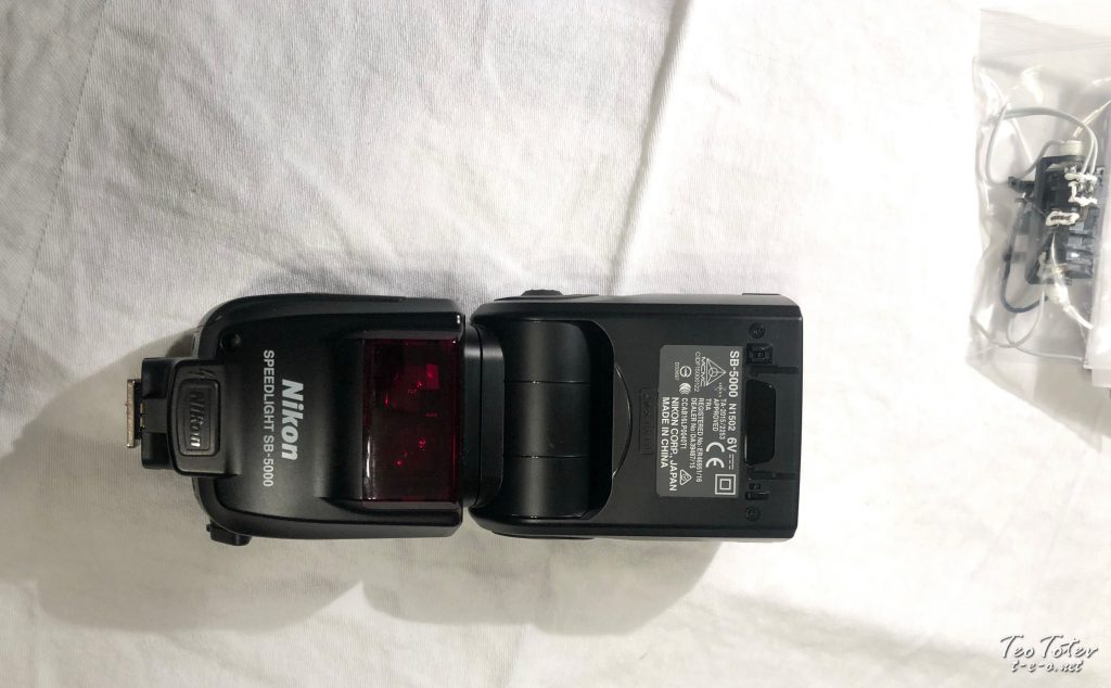
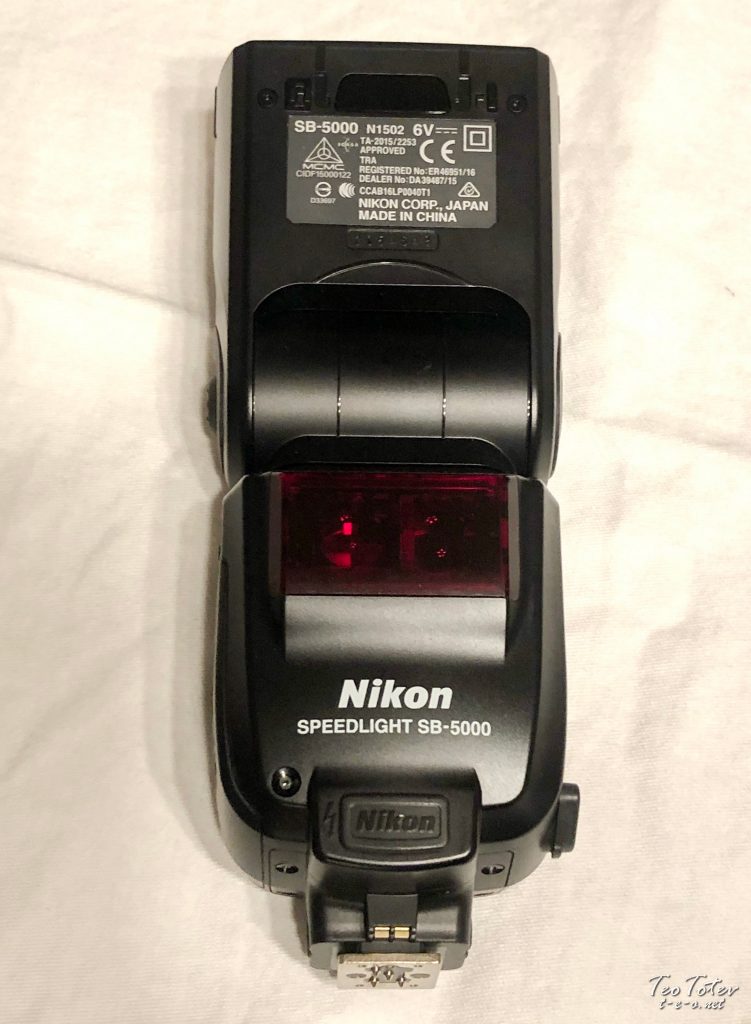
Here it is flash before repair.
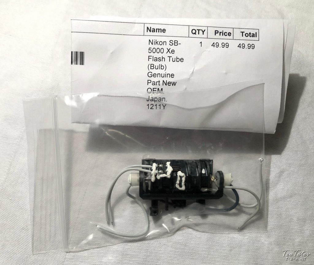
And the Flash Tube part itself. Part number is 1211Y and I have purchased it from ebay for 49.99$.
In old flashes Nikon SB-900 and Nikon SB-910 information technology was possible to supplant only xenon tube for few dolars, only in SB-5000 whole assembly have to be replaced with genuine part.
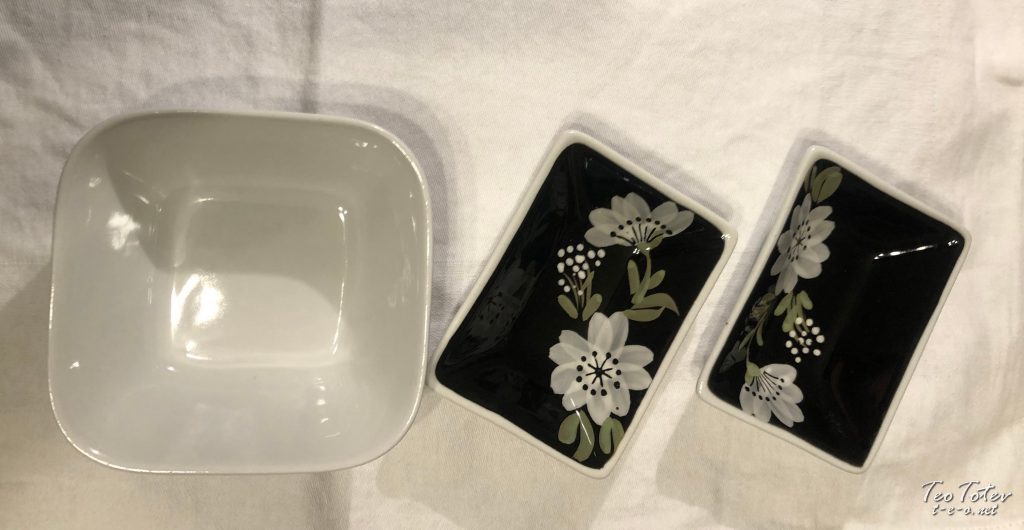
Pots Which I used for collecting small parts and bolts during disassembly process.
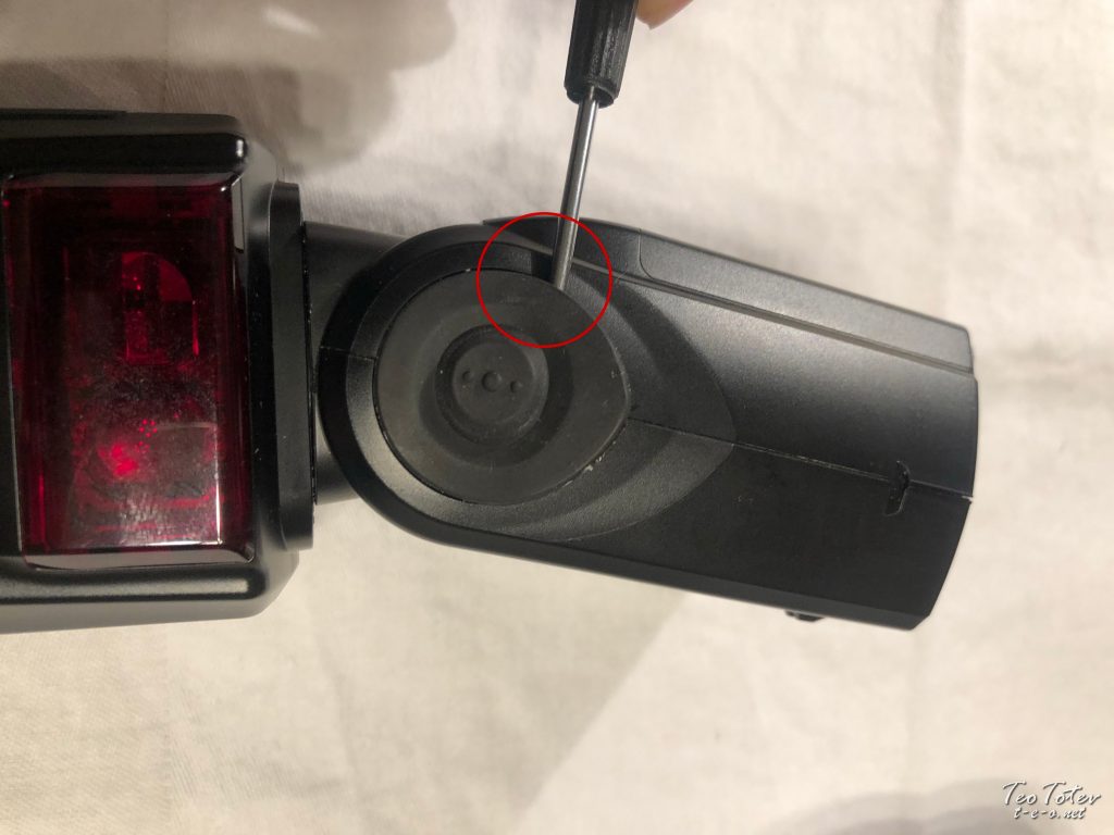
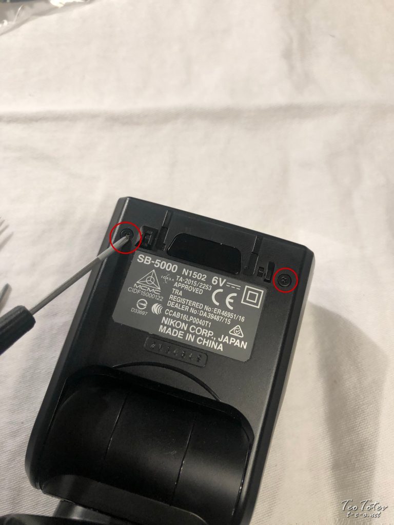
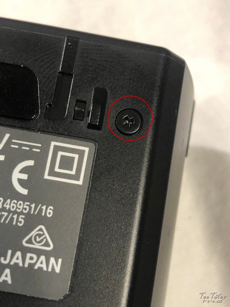
After you rotate flash head at 90 degrees first step is to remove rubber seals on both sides roofing set of bolts.
Do not afraid how you will glue them subsequently, they were with viscid substance themselves so no glue was necessary.
For removal I used flat head screwdriver.
Removing Flash Condom Seal on other side of the wink.
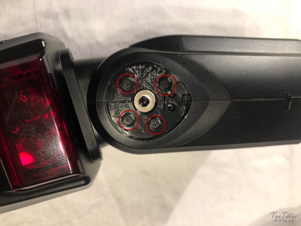
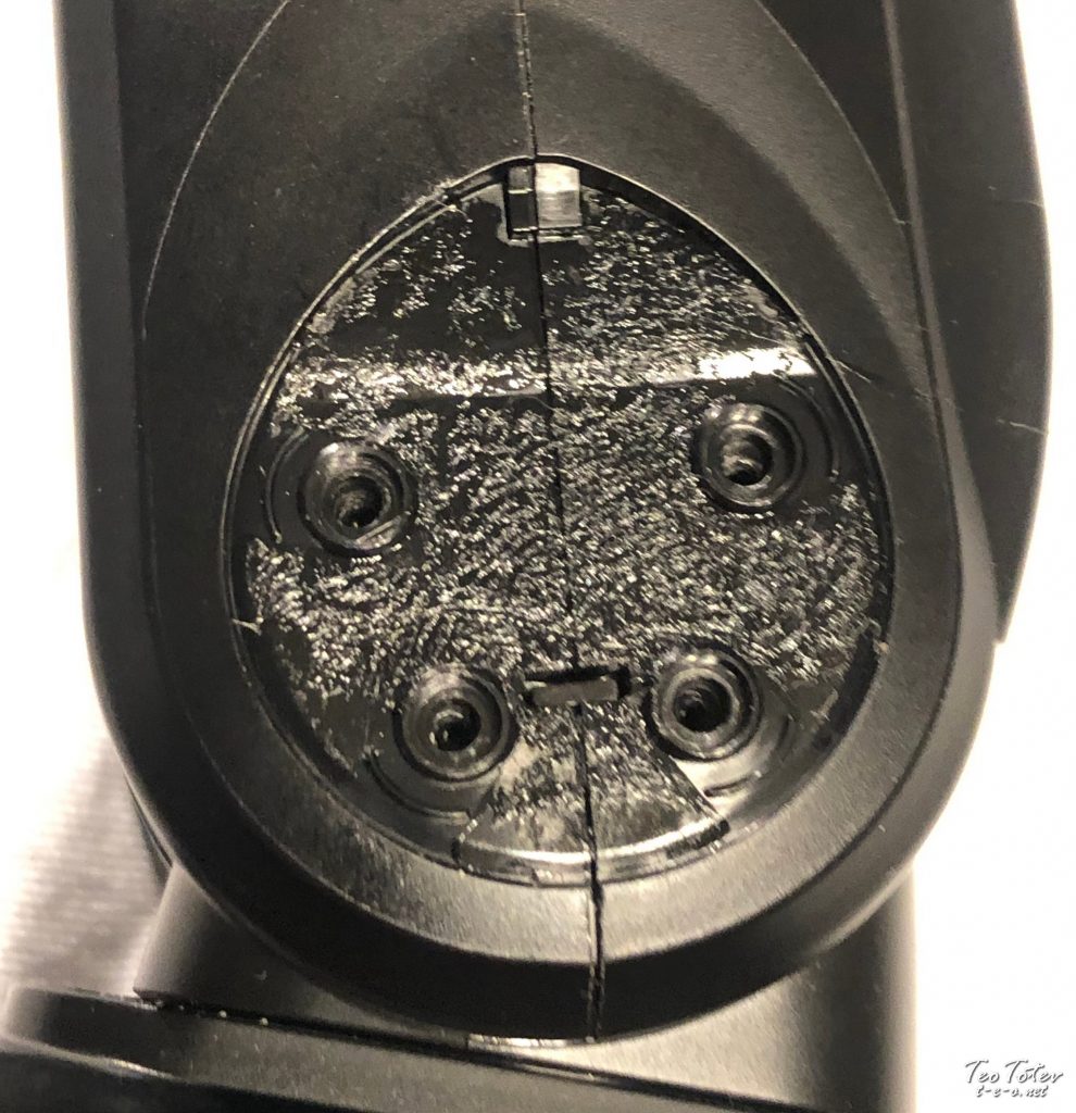
4 Bolts for removal from i side.
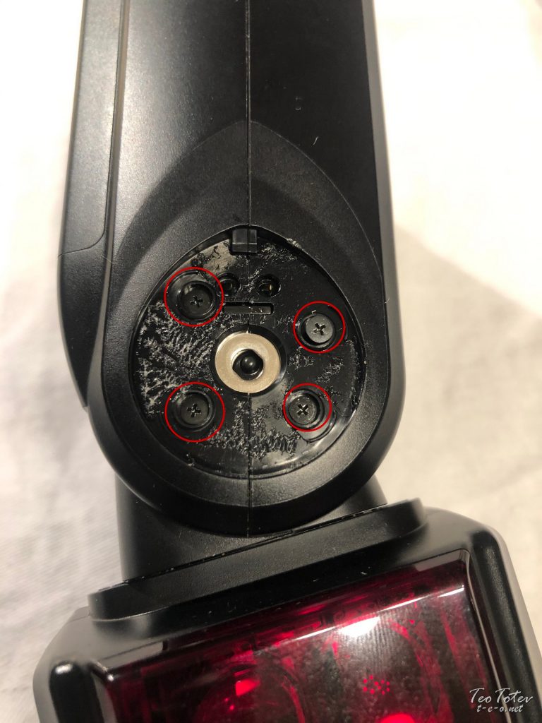
And 4 screws from other side.
I used tweezers to remove screws non to loose them as they were very tiny.
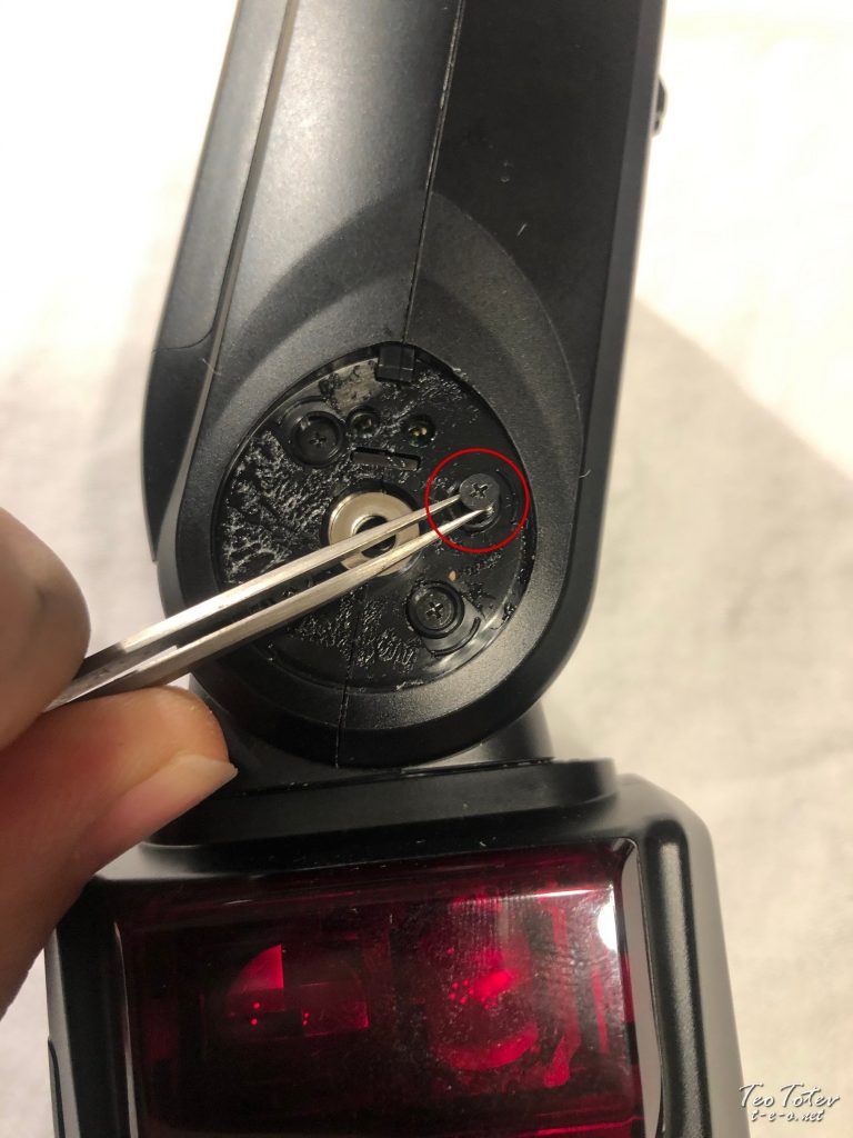
Spring push for wink tilting. Yous have to be careful with this 1 when you are disassembling and assembling dorsum.
Side view of speedlight with screws removed.
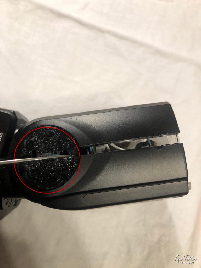
Special three pongs / 3 wings screws which Nikon have put brand SB 5000 disassembly difficult for boilerplate DIY.
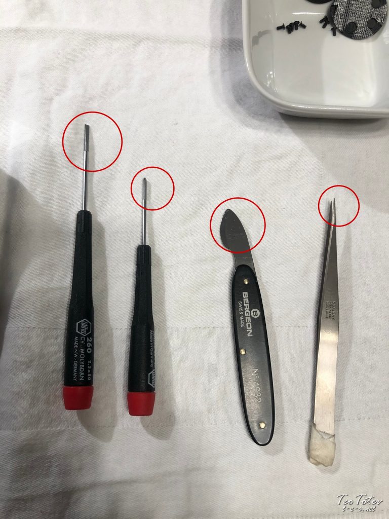
Tools used so far for repair.
Wiha Molybdan Screwdrivers
Bergeon N4932 Knife
Dumont Hi-Tech Tweezers
Using quality screwdrivers is essentials as one damaged screw tin bring big troubles.
Closeup on 3 Pong Screw on Nikon Flash
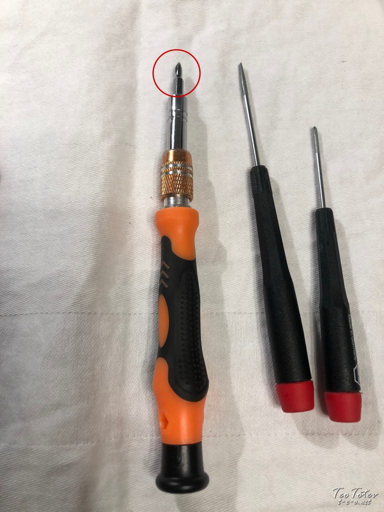
Zacro screwdriver which I used to unscrew three pong screws with size 3.0 tip.
Opening of wink with lookout man knife with blunt edge.
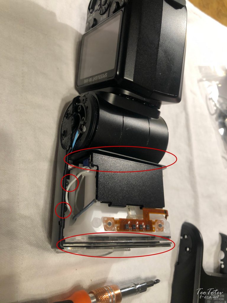
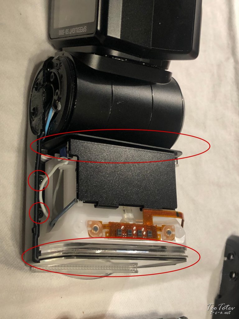
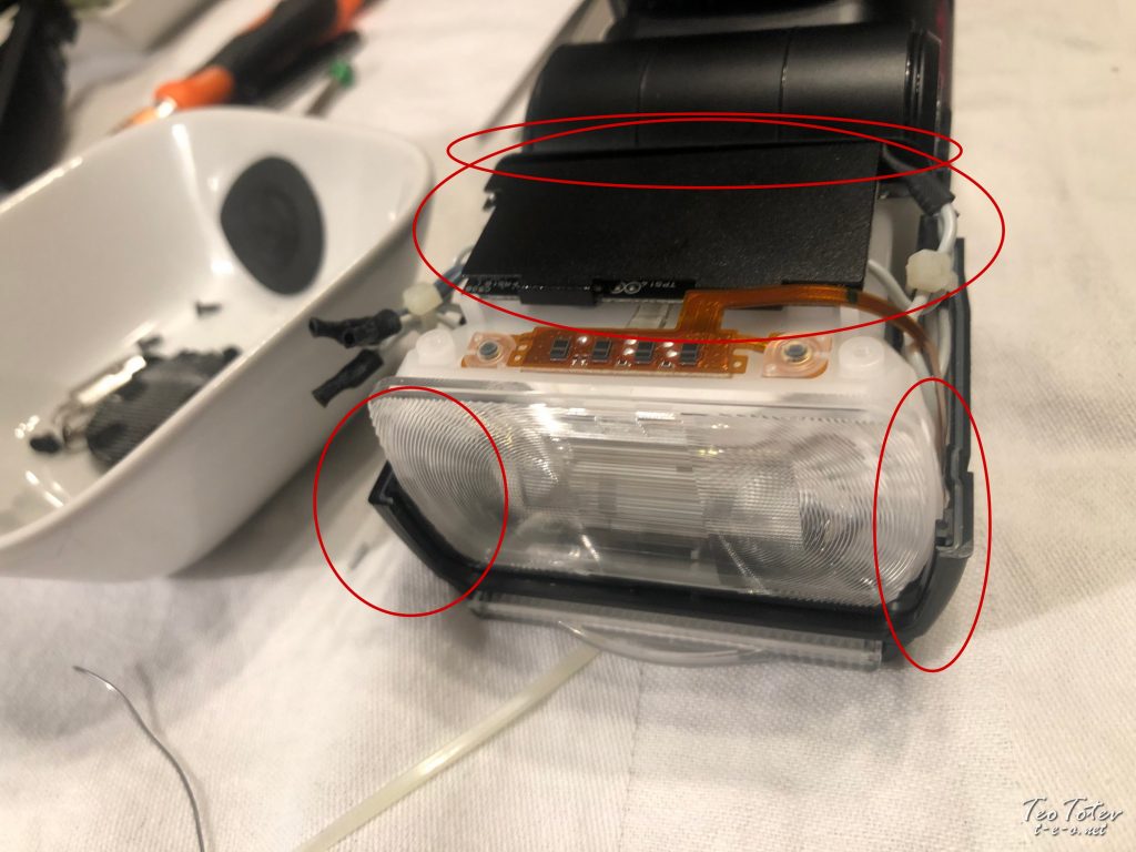
Keep special attention to orientation of freshnel glass /2 parts/ and likewise rear blackness divider. At that place are also 4 screws /2 on each side/.
A bit more closeup photo.
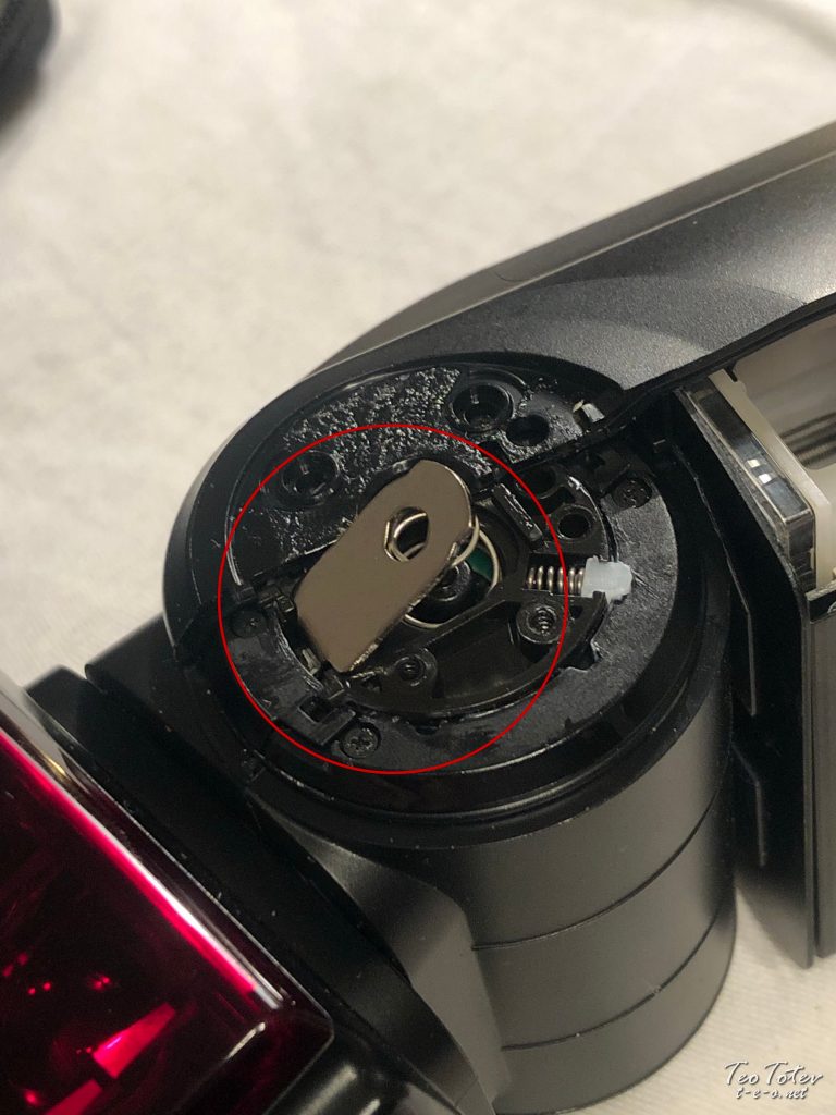
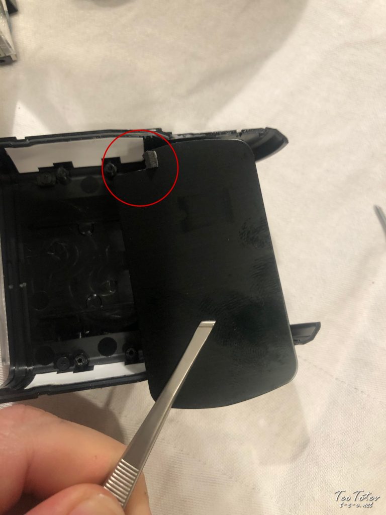
Be careful not to loose this metallic plate which is spring loaded and deed as release mechanism for tilting the flash.
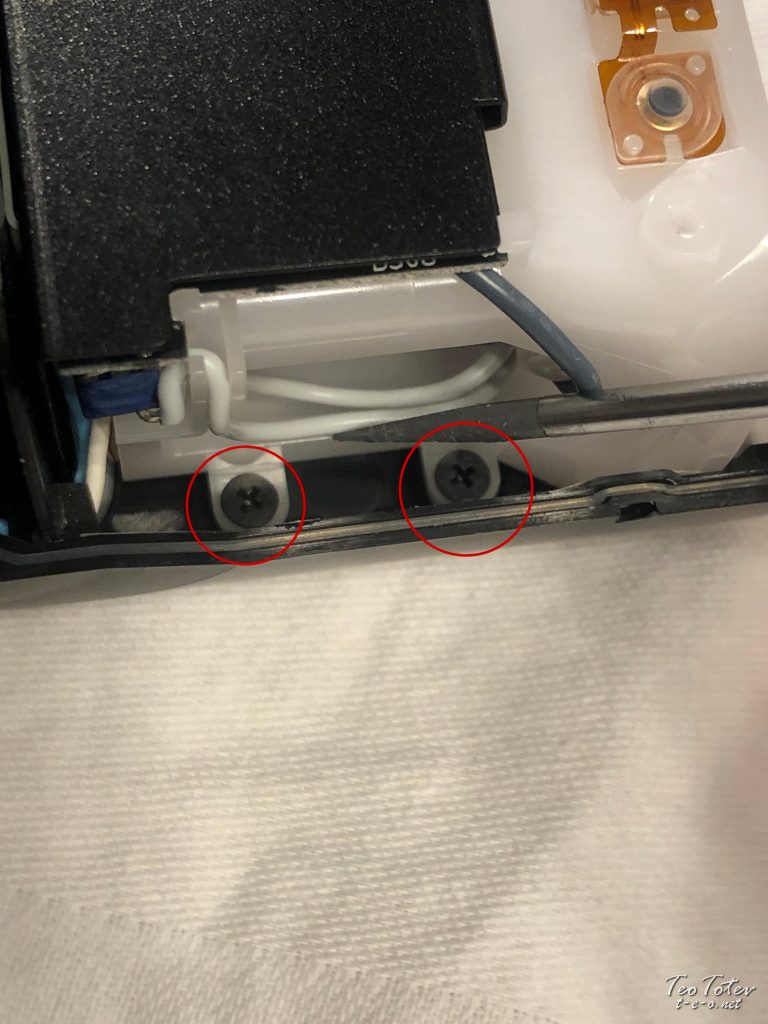
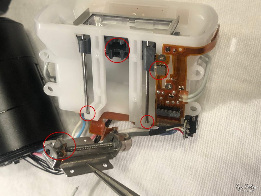
Hither you can see side screws which are quite hidden inside the flash.
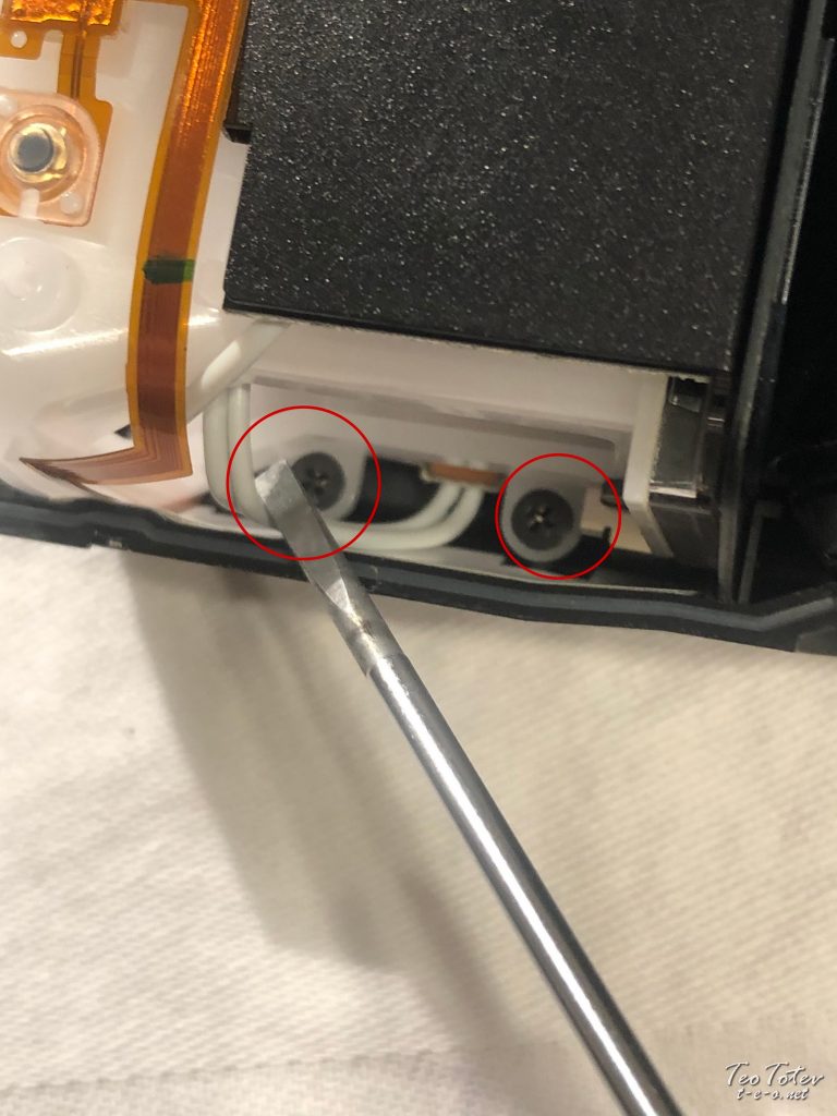
Other two on other side of wink.
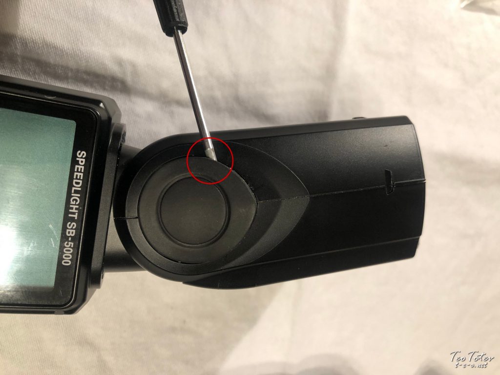
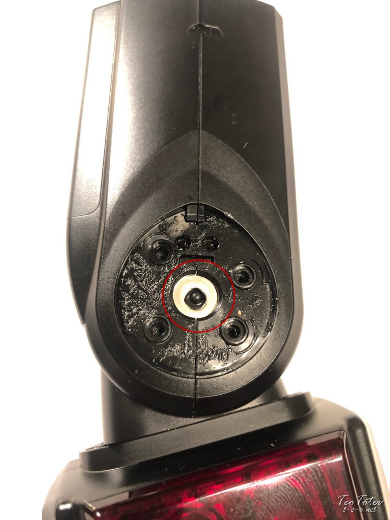
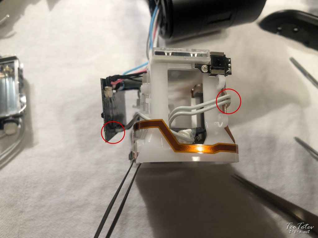
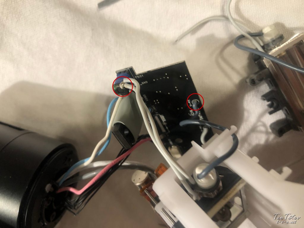
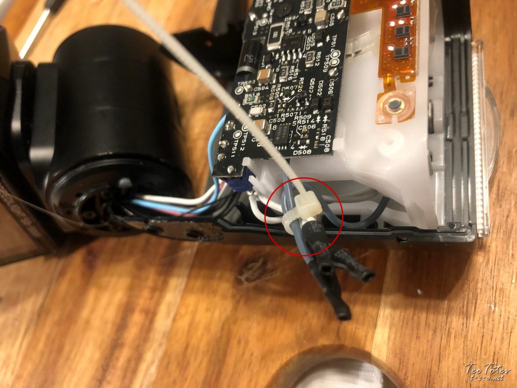
Keep attention to way barrier in middle of wink is put. Cables are passing where is red circle in photo above.
Side by side step is to remove viscid tape holding this isolation part effectually flash head and PCB.
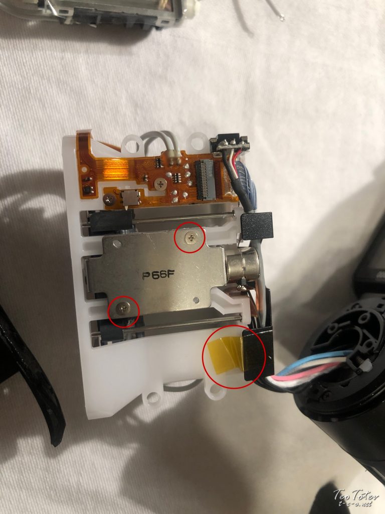
In Lower end of photo yous see sticky tape holding insulation role and and on left side are two screws holding motor of wink.
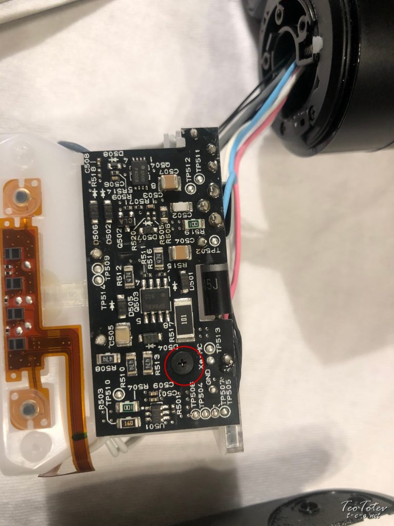
Acme PCB of Nikon SB-5000 and marked screw which is holding it.
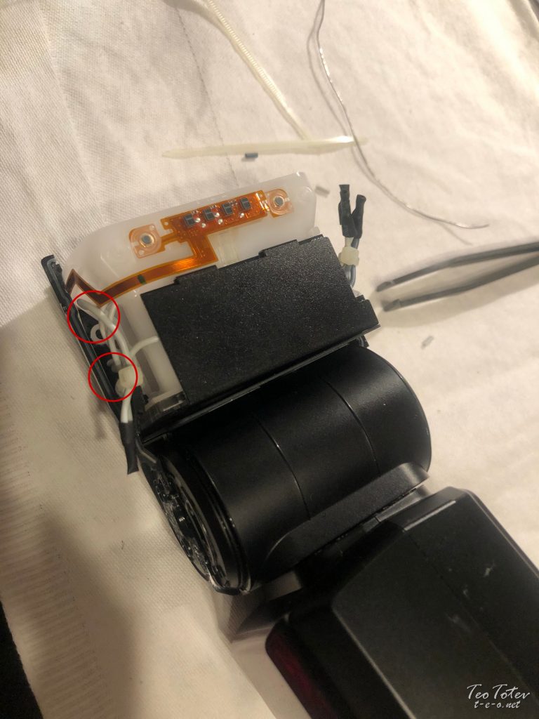
Accept note where cabling are going from each side of wink tube.
There are total of half-dozen cables, 3 from each side.
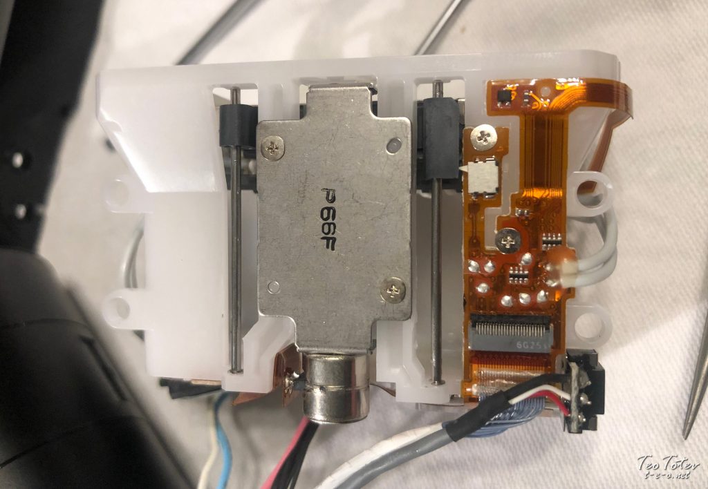
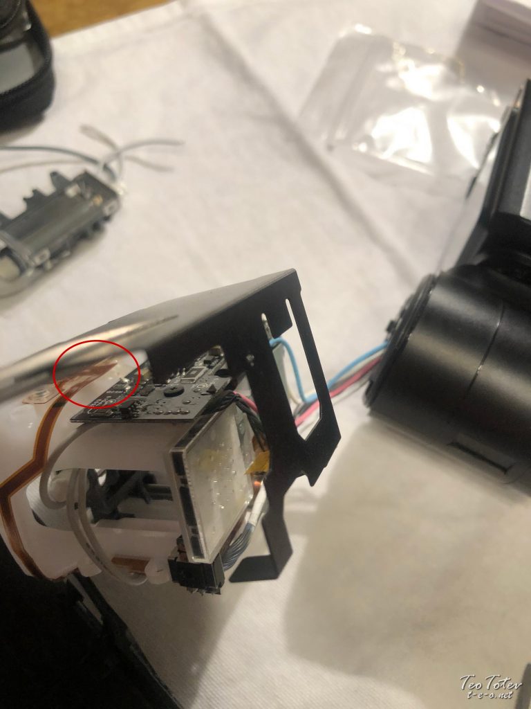
Summit view of assembly. In centre is motor and on right side are cables soldiered and glued on top. And this is side by side to very tiny chip.
Actually bad news for re-soldiering and repair.
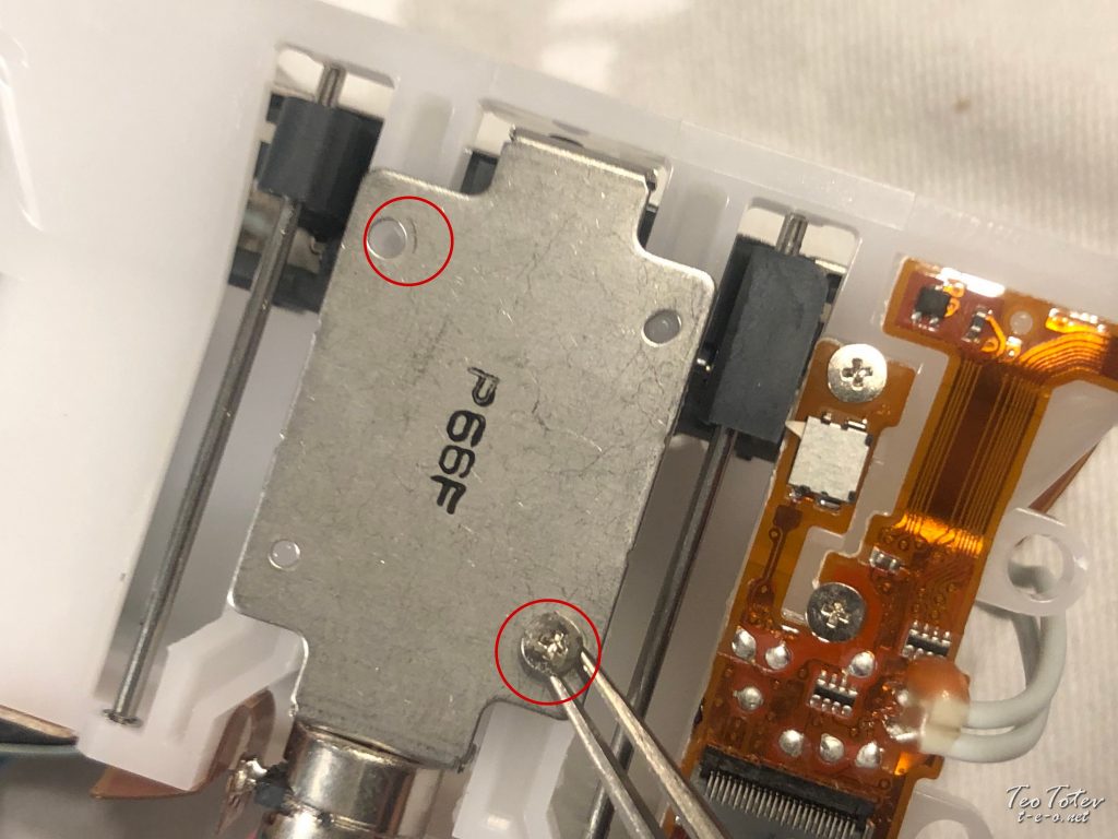
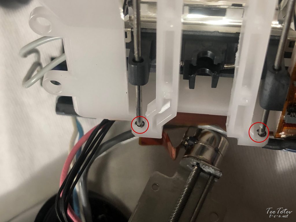
You can meet motor assembly here with summit screw already removed and removing 2nd screw carefully with tweezers after unscrewing it.
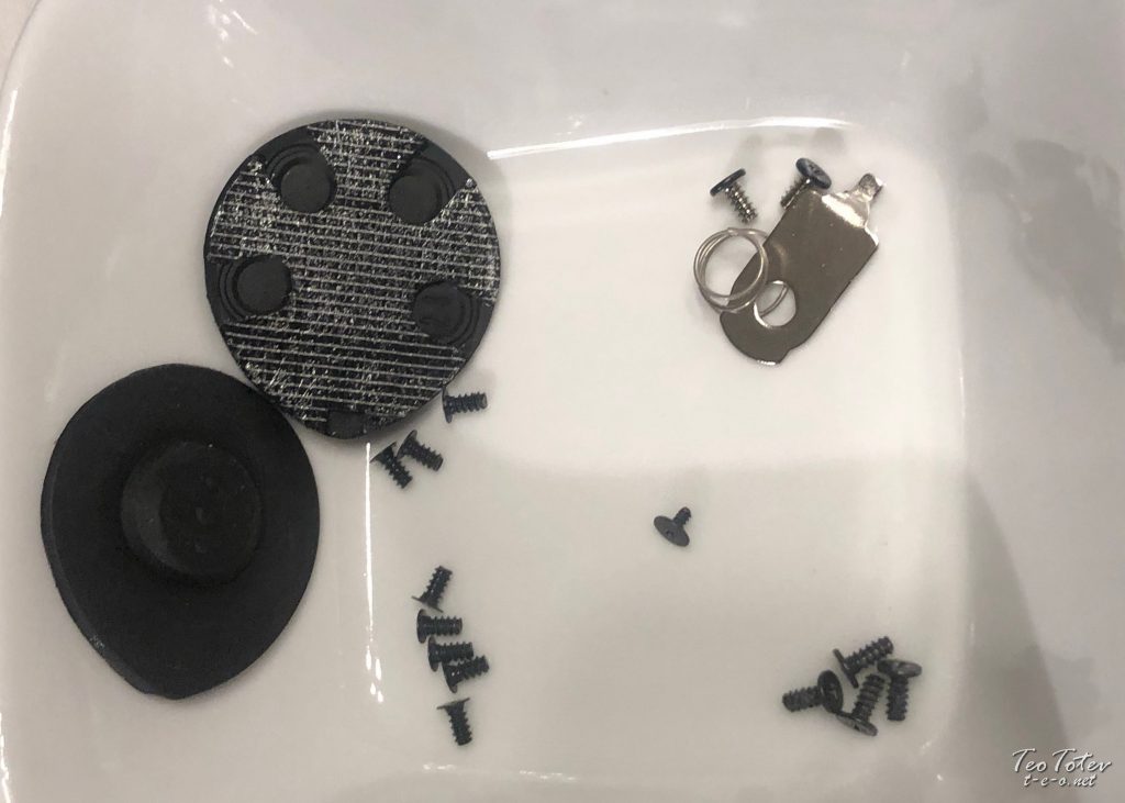
These are screws and parts which I accept in my office pot so far. Not a lot only it took me expert time to reach this bespeak.
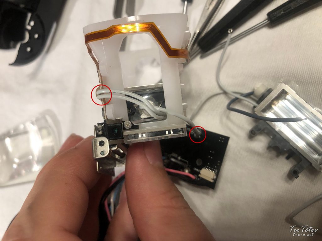
In elevation center you meet where motor is pulling xenon tube assembly. Don't forget to set it in same mode with new tube assembly.
On right there is pocket-sized sensor which is very fragile so be extra carefull with it.
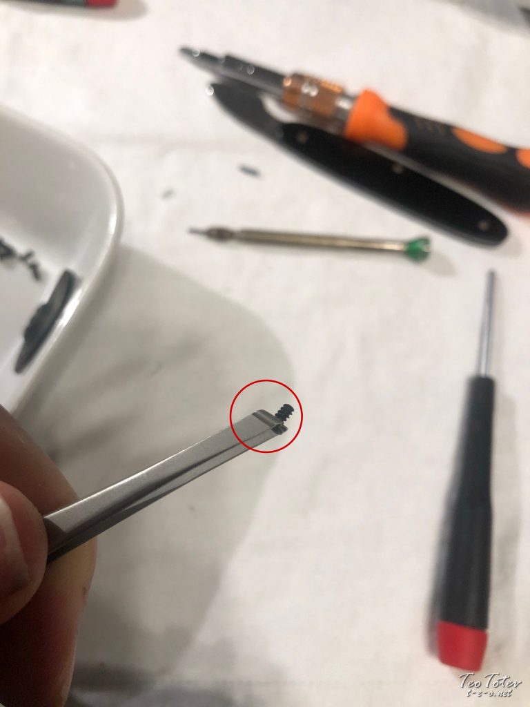
On bottom are 0.6mm e-clips which were very difficult for removal.
I used very small watch screwdriver to pull them, but unfortunately one of them become bend.
While I was trying to straighten it, it fly abroad and with its microscopic size information technology wasn't possible to found.
Then I was put betwixt two choices:
– to wait few weeks for replacement
– to gear up it in another way
I choose second choice for which yous can read beneath.
Hither are these extra special 0.6mm east-clips #047 /office number BS810-047/ if you want to order them.
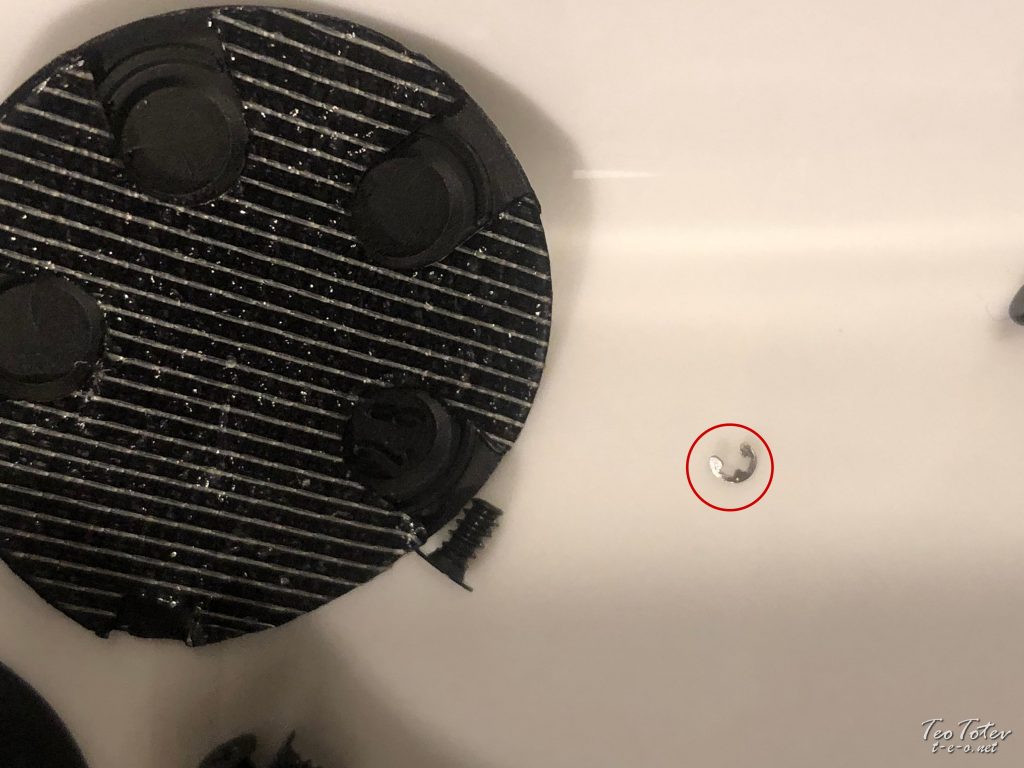
You can see how tiny is the e-clip compared to bolts and flash rubber seal.
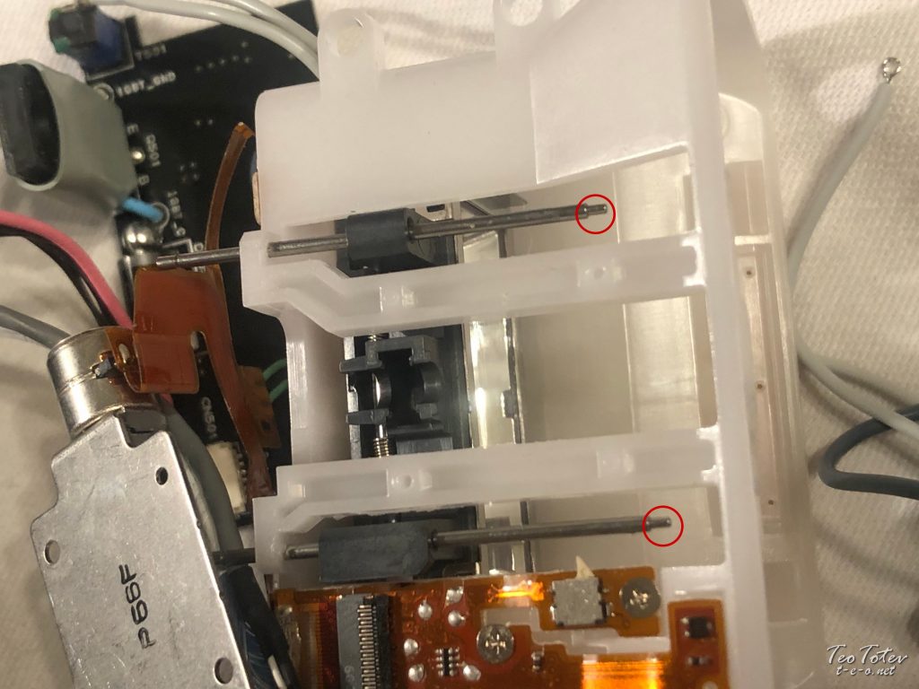
Here you tin see drive shafts and place where e-clips were placed preventing shafts from any moving or slipping.
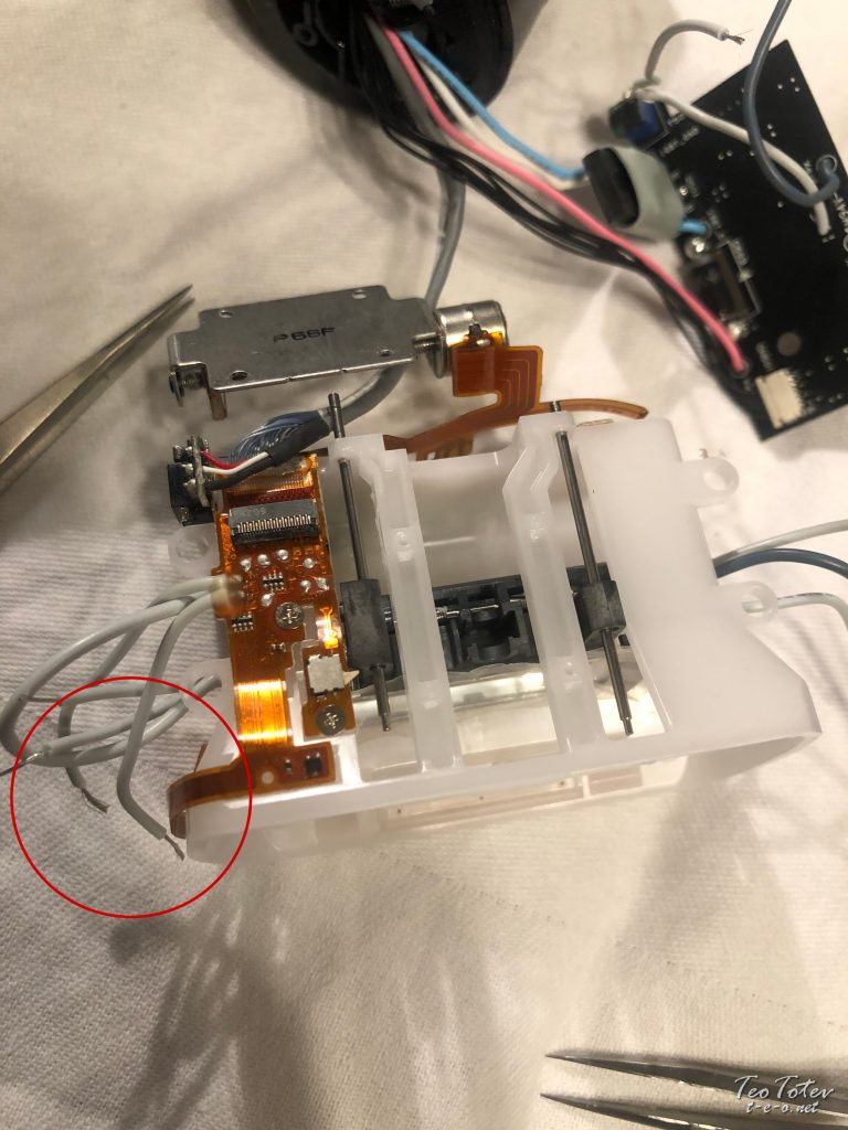
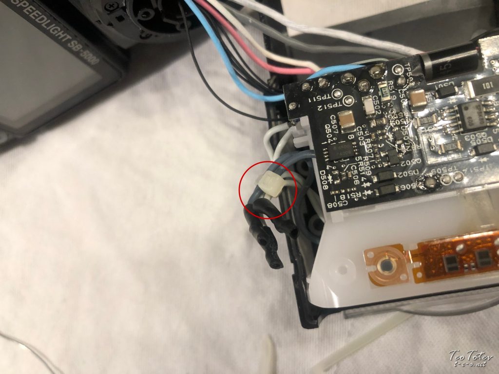
I took a photo and so I can run into later which was place where cables connect to PCB from flash tube.
Again, in that location are iii cables on each side.
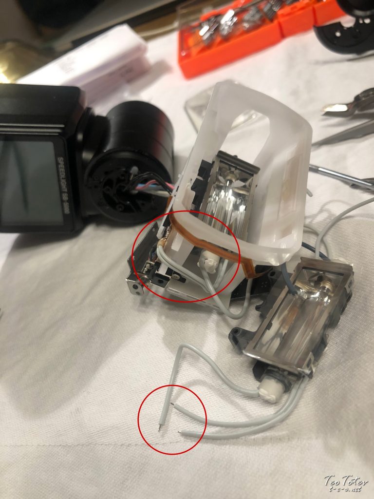
Already installed cables and comparison with ones in new flash xenon tube.
As you tin see in center of photograph cables were soldered and glued next to very small bit.
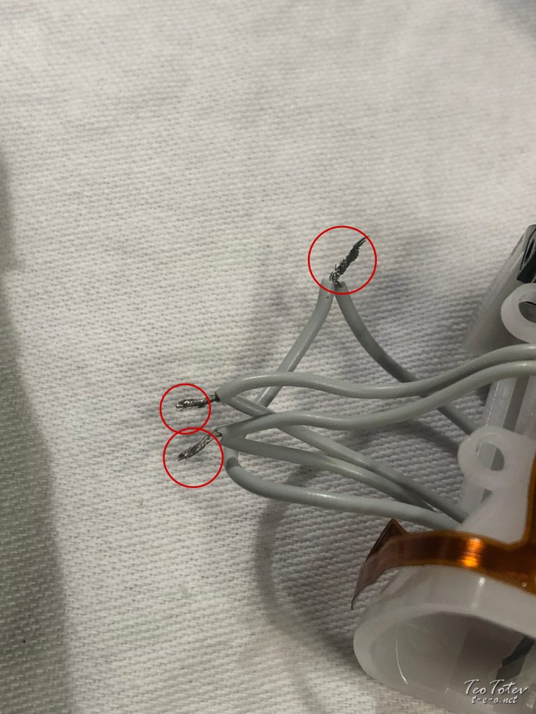
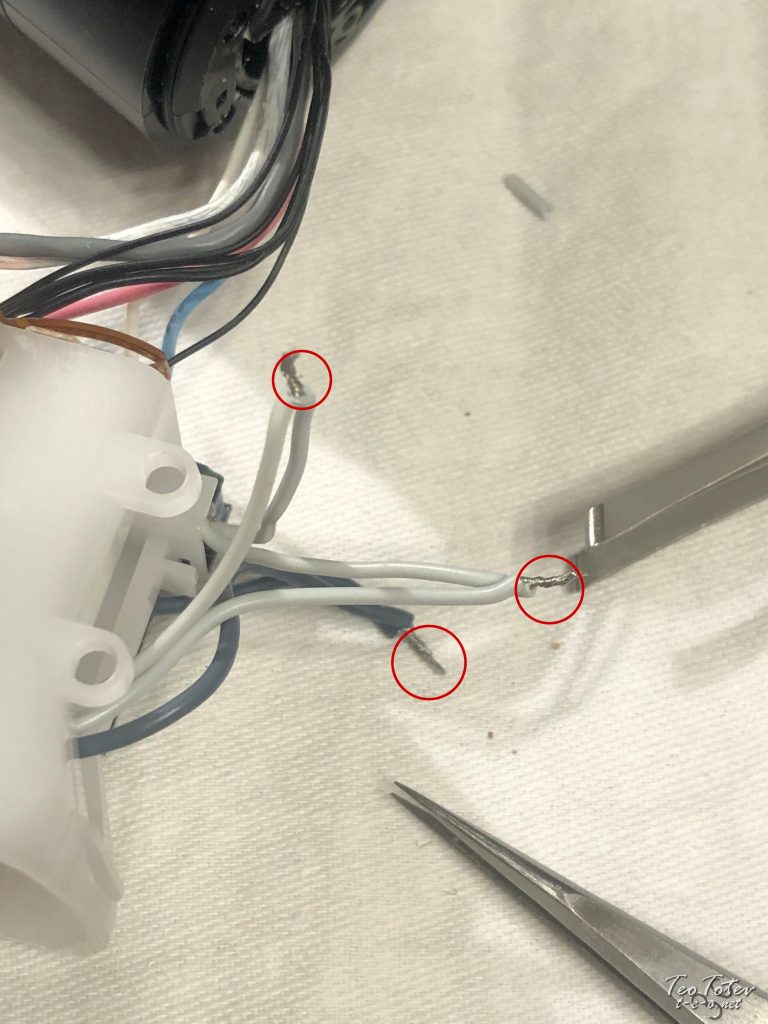
Then I decide non to solder them on PCB, merely to strip cables and solder them on the side.
As if I harm this chip with heat information technology will exist expensive to replace PCB as well.
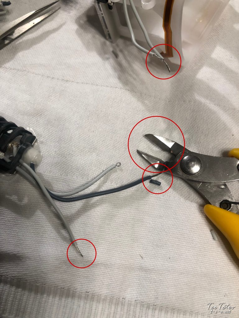
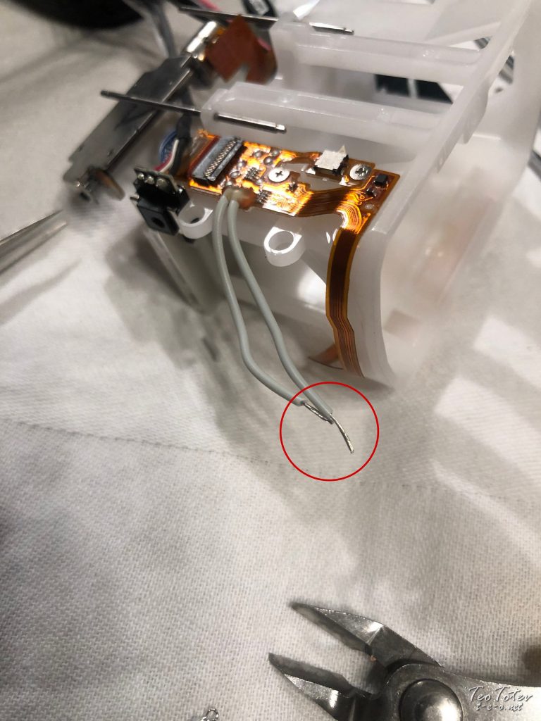
I used cable stripping tool to strip cables.
After I put new Xenon tube associates on drive shafts I have left cables on side to connect.
This was most difficult part of Nikon Wink Tube Replacement.
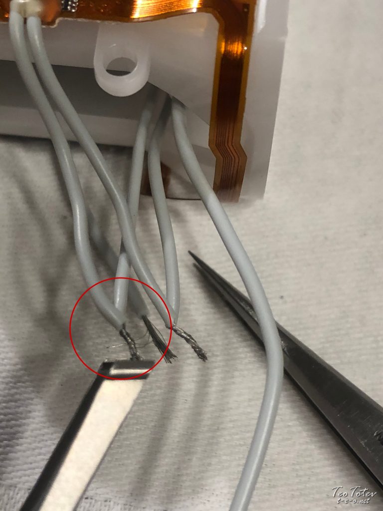
To have secure connections I did first cable twisting with tweezers.
Here are all cables on one side gear up for soldering.
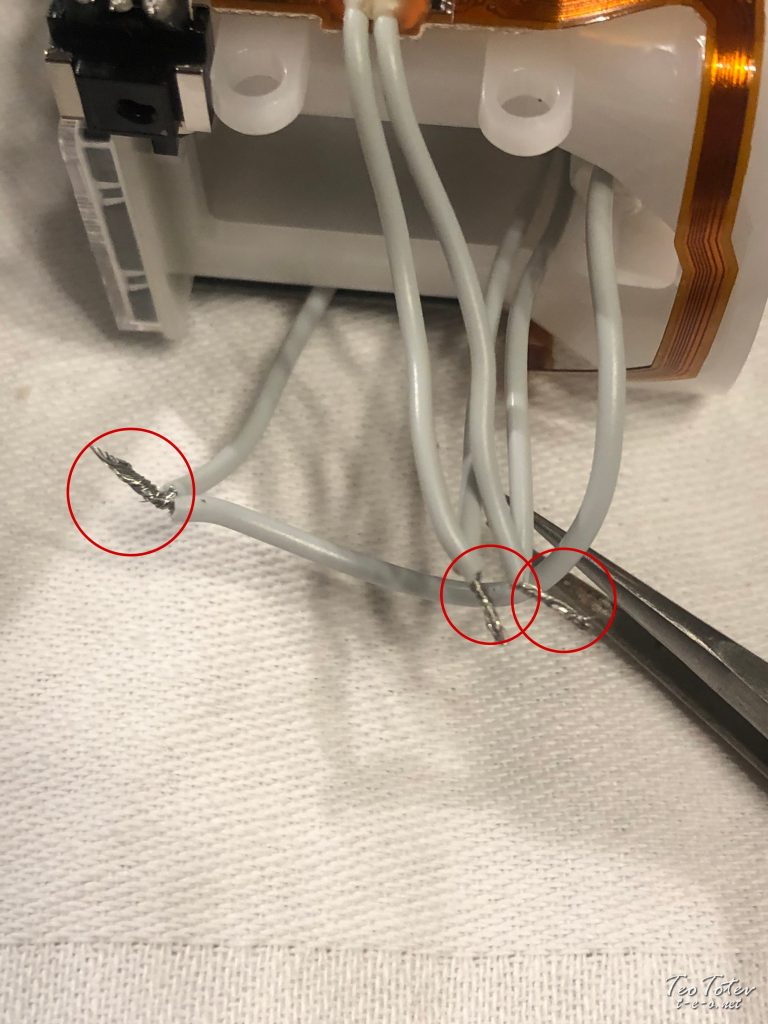
Soldered Cables on i side.
Soldered cables on other side.
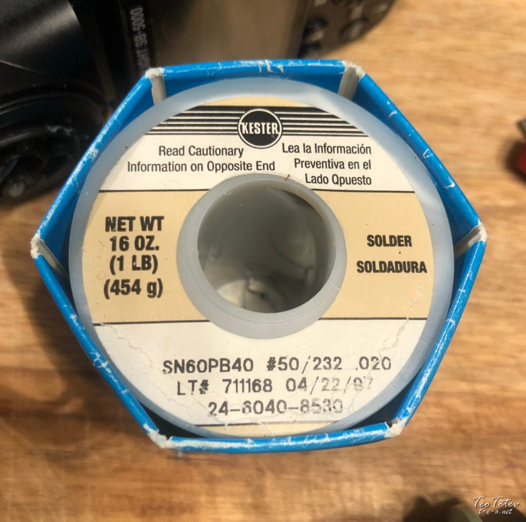
All soldering was done with Kester SN60PB40 solder. Good quality solder is making work very easy.
For audio connections I usually use solder with silver /Ag/ only information technology require high temperature to work so not best for sensitive electronics.
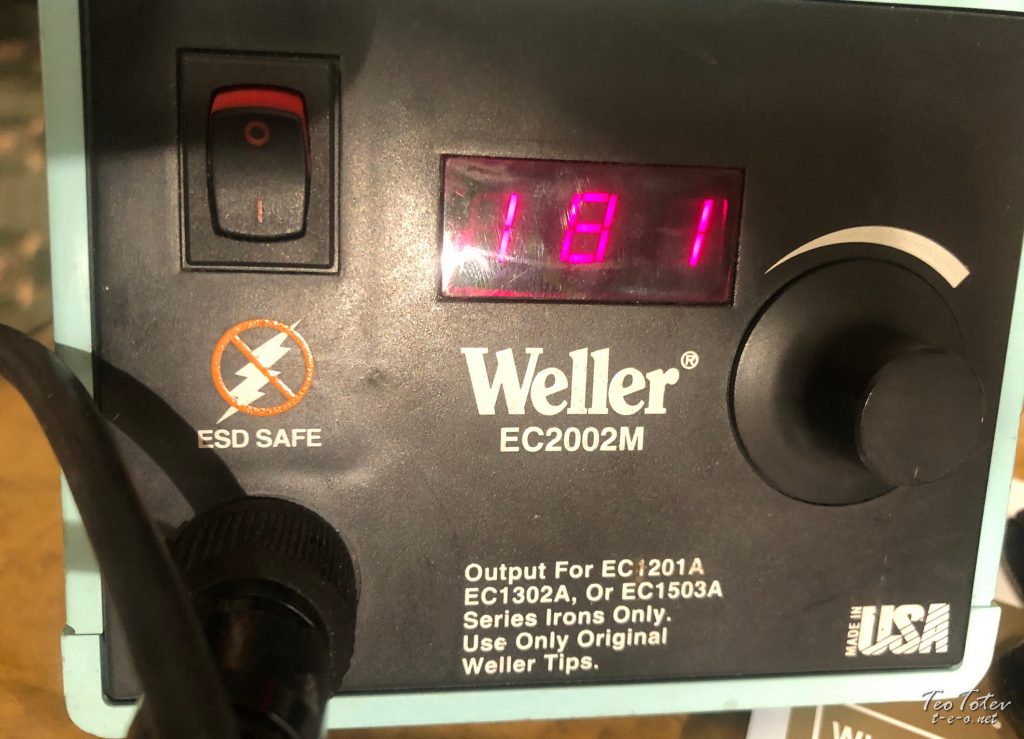
And my Weller EC2002M soldering station.
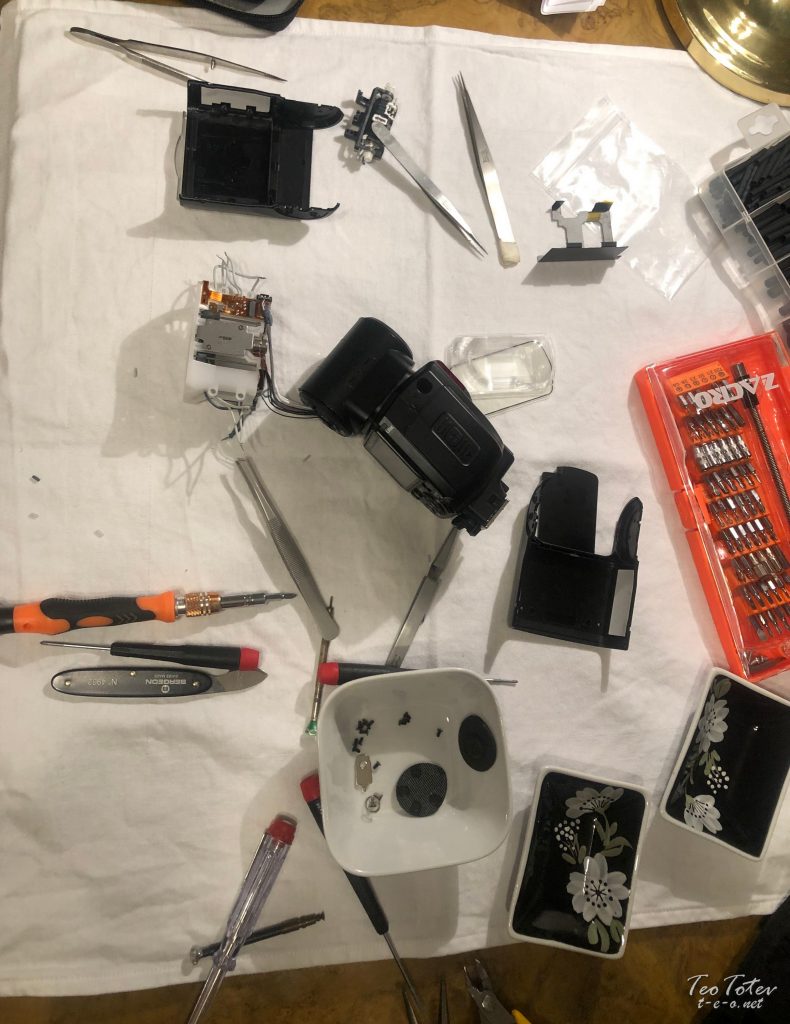
Here you can see most of tools which I used during repair of Nikon SB-5000.
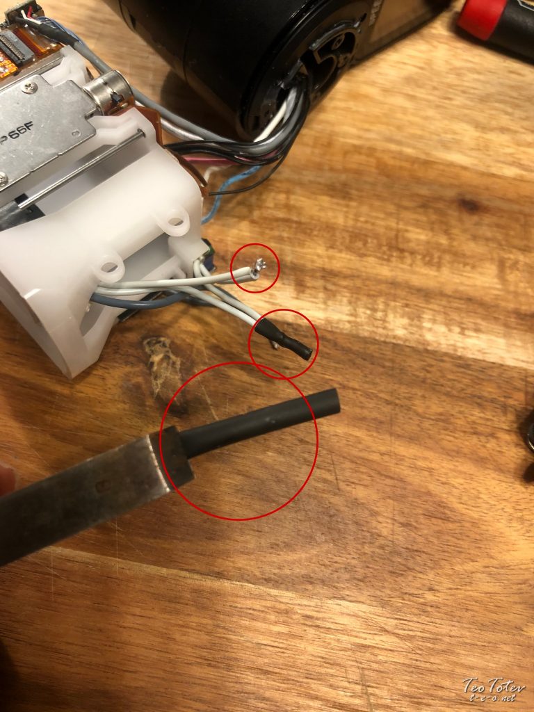
Next step later soldering was to put heat shrinking tube on peak of cablevision connections.
It is easy to be done if you hold tube/cables with big tweezers.
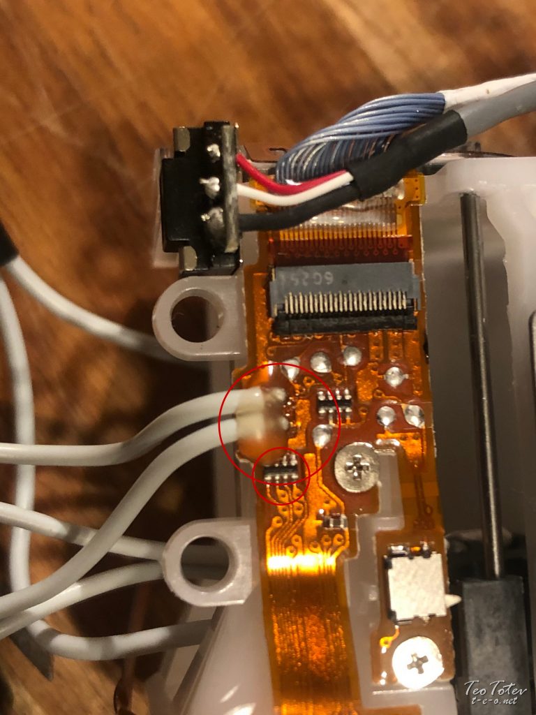
I forget to evidence this motion-picture show earlier, but this is why I cull to solder cable outside of board.
Offset in that location was glue on top of cables, and over actually small scrap.
Then damaging it while removing glue and soldering was existent danger.
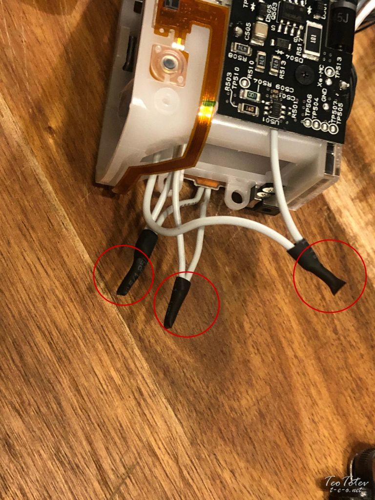
Here are heat shrinking tubes which I have pug on three of the cables connections.
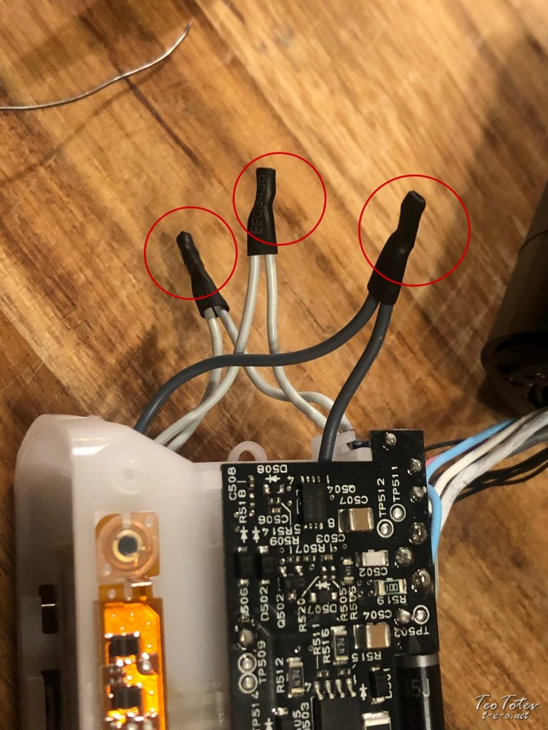
And 3 cables from other side later on soldering and roofing with tube.
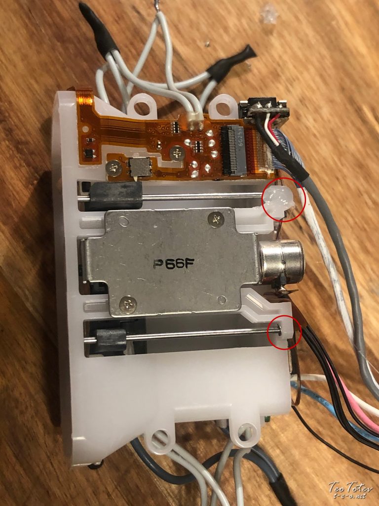
To gear up bulldoze shaft without missing 0.6mm e-prune I used hot glue.
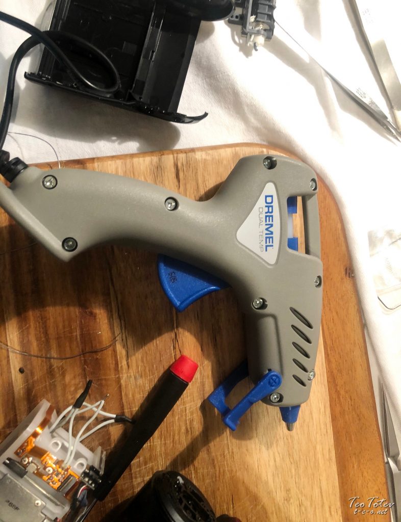
I take applied it with Dremel 930 Dual Temperature hot mucilage gun.
I used lower temperature gum sticks and gun prepare at lower temperature.
Before I was using no-proper name Chinese glue gun, only information technology was very hard to make whatever precision put of glue with it, and Dremel 930 make a large divergence.
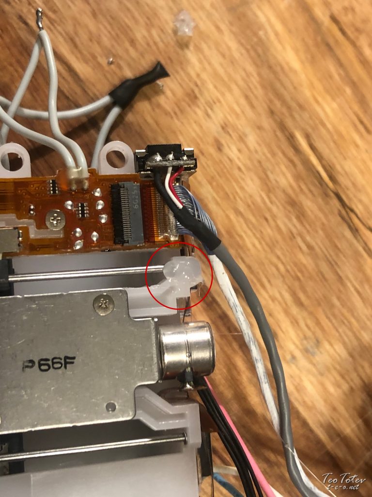
Closeup of silicone /hot gum/ which I have put.
Side by side step was to use cablevision necktie to hold cables together.
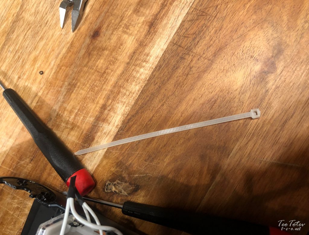
Here it is size of cablevision tie which I user for repair.
Don't forget to cutting cable tie to shortest possible length.
Associates farther was much easier.
Spiral 2 screws on each side.
Put blackness metal divider behind flash.
These are special tweezers which I used for holding screws to put them in tight places.
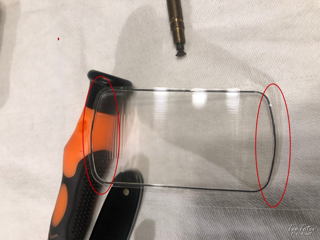
Before putting back glass fresnel see which is correct manner.
Every bit even information technology looks same on top/bottom, side shapes are different and there is but one right way you tin assemble it.
So hither it is drinking glass fresnel slided in, back divider as well in place and blackness plastic protector put on.
So from here there were simply to put two screws on superlative, and 8 screws on side and wink was fully assembled dorsum.
With this Nikon Flash Tube Replacement of my Nikon SB-5000 Speedlight have completed.
If you would like to find more and to run into more of my photography work, please visit primary part of my Website. For whatever queries and bookings please contact me. You lot can also find me on Facebook, Twitter or Instagram.

How To Repair Nikon Sb-e Flash,
Source: https://t-e-o.net/nikon-sb-5000-flash-repair/
Posted by: gonsalestheadis.blogspot.com
0 Response to "How To Repair Nikon Sb-e Flash"
Post a Comment